Going beyond digital in Digital Electronics experiment
The guide sheets for the Digital Electronics experiment are here (link on Faraday)
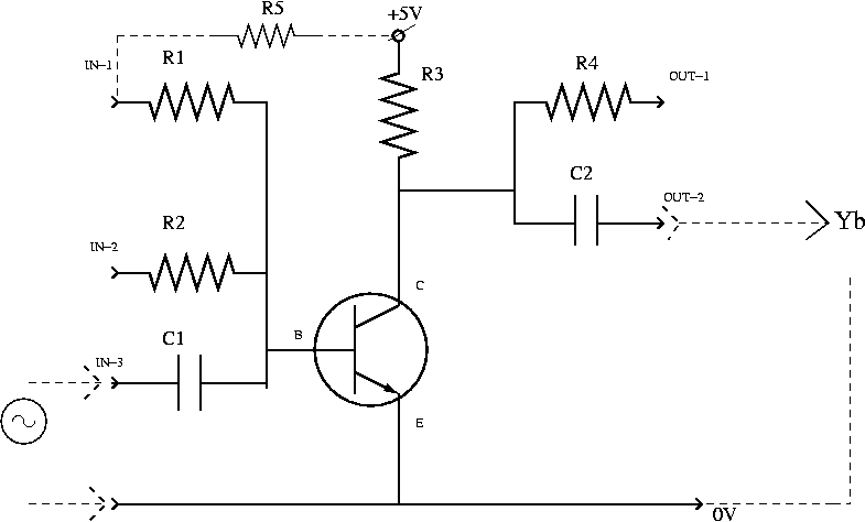
In the figure below you see the scheme of the basic 'black box' of this experiment.
I intend to introduce you to a nice extension of this experiment. You may use the 'black box' to study the behaviour of a primitive one-transistor amplifier.
How?
First, we drop by to the guys doing DC-I and borrow for a while their
box of resistors.
Secondly, we wire up things according to the diagram above.
If we want to study
the behaviour of the transistor in the transient zone (by transient I mean
not "0" and not "1" - those are the regimes you get if you follow
the guide sheets for Digital Electronics) then we have to find a way
to keep the transistor "open" (we do not want "1" at OUT-1),
but not too open (we do not want "0" at OUT-1).
One way to achieve the opening of the transistor is to connect
a resistor (R5) between the IN-1 and the +5V slots.
The practice shows that R5 = 1.8 MOhms does the job well.
I have tried smaller values from the resistance box, but they all
"push" the transistor in the "too open" regime we decided to avoid.
You may check at this stage the voltages (with respect to the 0V line)
at IN-2 (or IN-1) and OUT-1.
Any surprises or coincidences?
Next step is to apply the input signal at the IN-3.
The reason we apply the
signal through the capacitor is that we want the DC component
to be separated from the AC one.
In the particular case I was working on, the amplitude
"peak-to-peak" of the input signal was 50mV
(as monitored on channel Ya
of the oscilloscope).
To get such a small value of signal
you may need to turn the amplitude regulator to the extreme left and
also press the Attenuator button on the frequency
generator (so that you cut by a factor of 10 the amplitude of the output signal).
You may, of course, try to use the variable resistor
(which is provided for the regular "Digital electronics" experiment)
to regulate the input signal; I personally find this step to be
an unnecessary complication.
The frequency I was using was around 800Hz, sinusoidal signal.
Well, we are pretty much done. The output signal of our "home-made"
amplifier is to be displayed on channel Yb. We
pick up this signal from the OUT-2 slot; again, it goes via a capacitor.
N.B.
Pay attention to
the common ground wire of the two channels !
Here is the list of "TO DO" measurements, once you are up and running with this setup:
I believe you can use the same "black box" to wire the transistor
in a "common base" circuit, not only as the default "common emitter".
My advice:
don't give back the resistor box to the guys doing DC-I. Not yet. :-)
Good luck!
Last revised: May 17, 2003
Written by Sorin Codoban