The guide sheets for the DC-II (Thermistors and Diodes) experiment are here (on Faraday).
| Voltage divider | Measuring diode's resistance: Method I Method II
1. Voltage divider (the trick)
As you may have observed while performing the experiment, it's pretty
hard to get proper measurements of the (V,I) curve for the diode
in the "forward direction". The voltage step is coarse, and you can
easily miss the tight interval of voltage values when the
opening* of the diode
occurs.
* By "opening of the diode" I mean that the current
through it is significant. Now, you may ask "significant relative to
what" ?
"Opening" is a colloquial way of saying that for voltage values
on the diode of less than 0.6 V (for silicon based diode) or 0.2 V
(for germanium based diode) the current through it is too small to
be of use for the other parts of the circuit. This "use"
doesn't apply
to the DC-2 experiment, in which we are looking after the voltage drop
on the diode itself :-).
The divider
provides a "fine-grain" voltage, in the sense that
with this circuit you
can get a much better resolution for the voltage measurements (i.e. a
smaller step for the voltage applied on the diode D).
How does it work?
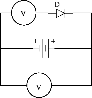
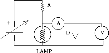
One has to plug the diode D according to the diagram shown in
Fig. 1. Now, assume you apply 5V (with the power supply) on the "voltage
divider" formed by the lamp and the resistance R.
Then, the voltage applied to the branch with the diode D is about
0.5V, which is exactly what we were looking for.
Please observe that most of the power supplies don't have a fine-tune
knob, so getting such a small voltage and varying it in small increments
is almost impossible without this simple device.
Note: observe that I connected the ammeter before the voltmeter.
2. Measuring the "resistance"
of the diode in inverse conduction
As you may remember from the experiment,
when one tries to get some
(V,I) reading for the diode connected in "inverse conduction"
nothing comes out.
Whatever voltage (U < 25V)
you apply on the diode, the current reading is 0.000V
(with the possible exception of some stray, fluctuating last digit).
Q:
Can we measure the "resistance" of the diode in such a case
(i.e. in "inverse conduction")?
First of all, we have to be aware
that the problem is perhaps ill-posed, in the
sense that most probably the
equivalent "resistance" of the diode is not fixed but
depends on the voltage applied
(like it does in the "direct conduction"
- although by a different relationship).
To put it in another way, the diode does not obey Ohm's law.
Nevertheless, it would be interesting to see how big that effective/equivalent
Rd is, and to estimate the leakage current (the current
flowing through diode in inverse conduction).
Right now I am thinking of two circuits that may help.
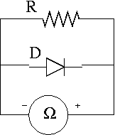
Case (A)
In Fig. 2 a resistor of large value
is plugged in parallel with the diode D.
Write down the value of total Rt given by the Ohmmeter.
Disconnect the diode D from the circuit
and measure again the value of the resistance with the Ohmmeter.
Obviously, in the first case the total resistance was given by
the formula for the parallel connection
Rt = R×Rd / (R+Rd)
while in the second case
the Ohmmeter was measuring just the R alone.
N.B. This was Rd for small voltages
(typically, voltage provided by the Ohmmeter is around 1V)
At least this is what you get with the standard power supply (with
only one knob controlling the output voltage).
Example: imagine a resistor connected in series with the diode, and the
whole setup connected to a variable voltage source.
If what you are interested in is the voltage drop
on the resistor (and that is usually the case in real world electronics)
then for input voltages less that the "opening"
threshold of the diode, the current is very small, and so is the
voltage on the resistor.
After the "opening" though, since the
current raises exponentially with the voltage applied on D, the voltage
drop on the resistor changes dramatically, and as you may convince
yourself the voltage on resistor will be the input voltage minus
approx. 0.6 V which is the voltage drop on diode (and it doesn't change
too much, even if the current increases by a factor of 10 or so).
I guess that one may agree (not trying to be too rigorous)
by looking at the (I,U) plot
(not Ln[I] vs U !)
that there is a
(rather fuzzy) threshold voltage, around 0.6 V, above which the
voltage drop on the diode is more or less constant, even though the
current varies by a large amount (one or maybe two orders of magnitude!).
Thanks are due to J. Leung for demanding more explanations
on this "opening" issue. :*)
For sure, this helps assess the region (0.3 - 0.8)V in which the interesting
things happen, namely the opening of the diode.
The resistance R is provided on the same box as the diode (typical
value R=1.2KOhm).
The lamp, also provided on the box, is the one used in
the 3-rd part of the experiment,
and has a "cold-resistance" of about 0.1KOhm or so. It
might be 0.05KOhm or maybe 0.2KOhm but the exact value is not that relevant.
The only thing that matters is that the lamp's resistance is about an
order of magnitude smaller than the value of R.
Moreover, one can see that a change of 1V in the voltage of the power supply
induces a mere 0.1V change in the voltage on the branch with the diode.
This is the "fine-grain" voltage step mentioned above.
You may think that this introduces an error of method (i.e. an error
due to the inappropriate circuit; see
my notes, written for DC-I)
since the current drawn by the voltmeter might be
comparable to the current which passes through the diode.
On a second thought, you may check that in our case,
with Rv = 10MOhms -
the inner resistance of the voltmeter, and
voltage drops on D around 0.5V, the current flowing through
voltmeter is about 0.00005mA.
Fortunately, this "leakage" current is (much)
smaller than the 1/2-digit reading error (=0.0005mA)
of the ammeter (say, on the 2mA scale
- which is the one usually used in this experiment).
The same apply if you consider the 1-digit error instead of 1/2-digit
(see the
specs
of the multimeter).
Hence, we don't really expect the error of method to be detectable/important, since
even if the Iv is comparable to the current through the diode
(which really happens when the voltage on D is close to 0V - you may
convince yourself that this is the case by looking at the slope of the V-I curve, for
very low V's), they are both unmeasurable. :-)
Nevertheless, I raised this
issue here just to prevent you from using a different circuit for measurements, with
the ammeter connected after the voltmeter. That circuit will definitely introduce
an error of method (at least after the opening of the diode occurs).
You may compare them, to see which one does the job better :-)
One option would be R=2.2MOhms, which is the typical value
of the largest (by value, not by size) resistance you can
find on the box from the DC-I experiment.
The other option, I'd say - a smarter one, is to use instead of R the
inner resistance of the second multimeter set as voltmeter (on the 2V scale).
It is known (see the
specs) that Rv is about 10MOhms, and
this
value fits perfectly our needs. Moreover, we avoid meddling with the guys
doing DC-I :-).
You may check that the Ohmmeter provides some low-voltage on its connectors
(use the other multimeter connected as a voltmeter,
to figure out which is the (+) of the
Ohmmeter and what's the value of that voltage).
If you are lucky (not required, but helps :-) ) you'll notice that the value
in the second case is a bit higher.
Perhaps by only a few last digits, but still, there is a difference.
Clearly, one may calculate Rd using the above two results.