As an example we take the DC experiment (part 1). In particular, we look at the setup for the parallel connection of the light bulbs
(see also fig.5, at pg. 56 in the Lab. manual).
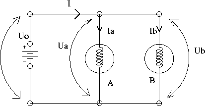
As you may recall, you are asked to measure the values of voltage drop across the:
a) battery: U0
b) first bulb (A): Ua
c) second bulb (B): Ub
If you work carefully, then you hopefully notice that the voltages across the battery and the light bulbs obey the relationship
U0 > Ua > Ub
The difference between them is typically about 0.1 to 0.3 V. This fact might be surprising at a first glance, since one would expect to find instead: U0 = Ua = Ub, as the theory predicts for the case of parallel connection.
One of the reasons for this mismatch is that there is some voltage drop across the wires.
Of course, the values of voltages U0 , Ua , and Ub by themselves are subject to errors as well (due to accuracy and/or precision of the V-meters), but at this point you are interested in the observed trend
U0 > Ua > Ub.The other phenomenon some of you observed happening, was that the battery had a voltage unstable in time (decreasing, for large current output). Although this effect really takes place, and is expected to occur, it cannot explain the observed inequality between the voltages (it may explain why they all drop together as you wait...)
It is now the time to check numerically that your guess for this source of voltage mismatch is indeed the voltage drop across the wires.
You have to give some numerical arguments for this.It is mandatory to sustain your discussion with numerical argumentation of your claims!
N.B. This discussion is one of high level (say, for A+ ) ; I don't expect you to do this in full at the first experiment. My example is intended to show you the extension and depth of discussions you have to achieve for the experiments to follow.
Getting the numbers
Method #1
Set the V-meter on the "200mV" scale and measure directly the voltage drop across each of the connecting wires and the bulbs. On the diagram of your setup (see above) write down all the voltages (across the wires). Keep the diagram neat!
Hopefully, with the voltage drops you just measured, the 2-nd Kirchhoff's rule holds with a better precision (I mean: the mismatch is much smaller than at the beginning, when you didn't account for the wires).Method #2
You take aside a few wires (4 or more), connect them in series, plug the multimeter as Ohm-meter and try to get some reading for the resistance of the wires. Of course, you have to choose the right range on the Ohm-meter ("200 Ohms" scale).
You'll get (roughly) for the resistance of 4 identical wires connected in series R = 0.4 Ohm.
Of course, you cannot really trust those digits; nevertheless they give us a clue that the resistance of the wires is not zero!There are a few reasons one cannot "really trust" this value for R.
The first one is that you work at the level of the last digit. For this scale, the accuracy error is (0.5% of the reading + 4 digits), the reading error being (1/2 digit). Hence, the value of R can easily be anywhere between 0 to 0.8 Ohms (!).
The second reason is that beside the "intrinsic" resistance of the wires, you have also resistance at the connection points (though, in this case, this might be negligible. Well, in fact you never know for sure, so better safe than sorry...).Nevertheless, all in all, roughly, you can probably assume that (2 wires + the connection points) have a resistance of about 0.2 Ohms.
Now, we go back to the currents we have measured, and we see that roughly we have
I0 =2 A, Ia =1A, Ib=1A.
Therefore, we may conclude that the voltage drop across the wires is about
dU = I×R = 1A × 0.2 Ohm = 0.2 V, which, hopefully is approximately equal to the difference you found between Ua and Ub.For the wires between battery and first bulb (A) you have a bigger current, so the corresponding voltage drop is even bigger.
Have you seen this in the experiment?Hint: to measure the voltage across the bulbs use the V-meter on a scale that provides at least 3-significant digits ("2V" or "20V" scales).
Conclusion:
You have to bring numerical arguments in the game, to prove that what you say is true!
N.B. As you may see, our argument was sustained by the large values of the currents through the wires. Although not explicitly, our reasoning was based on the small values of the resistances of the light bulbs, which was comparable with the resistance of the wires (only about one order of magnitude between them).
If, in the part (2) of DC-I, you try to "blame" the wires for this type of mismatch it won't work!
That's because there the currents have 10 to 20 times smaller values, the resistors you're using have resistances of hundreds of Ohms or more, so the resistance of the connecting wires doesn't play any significant role.
Last updated: May 16, 2003
© 2003, Sorin Codoban